
03/20/2012
When the RC sailboats with chine continuously have greater success than sailboats without chine I thought: should have more reasons than those already known as to improve the displacement of the LCB due to decrease in volume when the side is immersed , decreasing the sinking bow.
And I began to study the heeled boats form.
After some assumptions I open a thread in the forum boatdesign.net about the possibility of obtaining anything about it.
My assumption was that the chine when immersed cut the waterlines so that the boat forms would be better hydrodynamically , improving the lift carried by the hull and improve the angle of attack required for the whole shell / keel develop the lateral force to counteract the lateral force produced by the sail.
Mikko Brummer a participant in the forum said: “I also believe there is something to the chine and the hull lift, my example being the Star. It has a very pronounced chine, but a shallow and basically inefficient keel with a large skeg in front of the rudder. In the VPP, which ignores chines and is not very good at hull lift, the Star is a lousy upwind boat, with a very large leeway up to 10 degrees or more. In the real world, it’s nothing of the kind, but a wonderful upwind machine beating at 70 degrees from tack to tack, while heeling close to a comfortable 30 degrees and the keel root intermittently in the air. So I would be surprised if its chined hull had nothing to do with it.”
Mikko sent me a drawing of the Star that I went to the freeship to analyze their heeled waterlines :

Mikko drawing


What we see: the waterlines are perfect asymmetric foils that can develop a force against the wind.
Then I do a design with similar form to Star:


I do another design modifying this:


Let’s see Riptide:

Riptide 10 degrees helled

Riptide 30 degrees


Riptide wl 35 degrees
 Although we see that the Riptide 10 degrees waterlines are in the form of foil, the foil is in the opposite direction it should be, the high pressure side is on the wind come side generating a force downwind.
As the shell heel, 30, 35 degrees, the foil is being formed on the right side, ie with low pressure side on the wind come side , generating a force against the wind.
Based on this I would say that the stronger the wind would be the best boat performance. I’ll ask Earl Boebert if this is correct. Earl was the one who sent me the design of the Riptide.
————————
Earl Boebert replied to me today (03/20/2012 – 15:26):
|
Originally Posted by fredschmidt
 EarlI am supposing that the Riptide performance was better in winds with more velocity than lighter winds. Am I correct?
|
Now we have another explanation than that of Mr Sponberg.
The rapid change in board side of low and high pressure may justify also leaps out of the water and the good efficiency in greatest heavy air can be explained with the adequate waterline forms at great angles of heel.
————————————–
I remember that the angle of attack must be better with adequate waterlines foil form.
Another thing to note is that the side of the Riptide is pretty straight and vertical, like a chine, which facilitates in larger angles of heel the proper formation of waterlines in appropriate form of foil.
Thinking about this subject I would venture to say:
1 – The chine improves the shape of the waterlines by placing the low pressure side from where the wind came. Both port and starboard.
2 – It also improves the angle of attack
3 – We must be careful when designing the hull, study it tilted so as to obtain good waterlines in the form of foil
4- There should be a better form of foil to the water lines.
Of course the boat design should continue to take into account:
1 – weight
2 – prismatic coefficient
3 – wet surface
4 – entrance angle
5 – LCB and LCF heeled positions – (referred to 0 degrees)
The set of all these factors chosen properly, will lead to the best boat.
I believe that the assumptions above, based on good sense, take the boat design more efficient.
Ideal would be to develop a research on the subject. For my part I will use them in my RC sailboats, and I will continue my studies on the subject.
A good contribution to the subject is to confirm this theory with whom designed good RC sailboats as Britpop!, Pikanto, Cheinz, Lintel, etc..
As this theories is valid for real boats, the real boats designers can help also.
==================================================
Continuing the subject of the heeled geometry of the hull, we see two hulls famous and efficients:
first:

- Boat 1 10 degrees
-

- Boat 1 35 degrees
second:

- Boat 2 10 degrees

- Boat 2 35 degrees
What we notice is a concern to keep the symmetrical shape of the heeled water lines, not to mention the design parameters, such as Cp, LCB, LCF, SA, etc..
The former has water lines near symmetrical but form a angle with the center line due to the large and flat transom and the second, which has much better performance than the first, the water lines angle with the centerline is lesser.
The research I’m doing as far as possible, is to investigate whether the water lines inclined in the form of asymmetric foil produce boats with good performance, with less leeway, better handling, lesser angler to windward, etc…
Here is my next RG 65, the heeled waterlines concept is totally different. My intend is do the heeled waterlines as asymmetric foils, with lesser angle possible with the centerline , maintaining the design parameters better possible. And here we need speak about chine:
the chine cut the inclined waterlines transforming them in asymmetrical foils in the right direction, with lift against wind and I used it in my design to optimize the foil.
To reach this at small angles I do the chine a little immersed in midship:

- Heeled hull foils 20 degrees

- Heeled hull foils 30 degrees

- Heeled Hull foils 40 degrees

- Heeled Hull foil 50 degrees

- 3D 30 degrees

- 3D 50 degrees
At the same time I will do an other RG 65 to satisfy an other curiosity 🙂 (with the same concepts above):

- Orca

- Orca

- Orca

Yes, I know, we can have a submarine, but engineering is to solve problems :).
I think that I am seeing Americas Cup videos in excess.
—————————————
08/17/2012
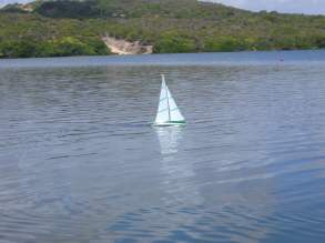
Orca videos:
I can not say that the hull made with waterlines in the form of foil is beautiful and wonderful. But I can say that the Orca goes well, points high, and has great maneuverability.
One thing is clear, the hull with heeled waterlines in the form of foil, it does not hurt.
—————————————————————
08/17/2012
We receive from Bob Wells the Seattle IOM Update Newsletter – Sept. 2012 with some Dave Hollom about the subject:
” A Theory on Canoe Body Lift from Dave Hollom – Must Read!! (8/6/12)
Dear Bob,
Firstly, thanks for a very readable magazine. I was particularly interested in the various articles about chines and thought that I might be able to contribute to the discussion.
The designers, Ian Vickers, Jeff Byerley and John Taylor, in one way or another seem to think that the chine allows the hull to grip the water, that it helps the hull to produce lift or side force and that the consequent reduction in leeway enables you to point higher. The aerodynamicist, Tom Spear, points out that even if it did, it is not efficient to produce lift from the hull because it is near the water surface and another anonymous reader agrees and also thinks that it is the bi-plane versus monoplane argument. The truth probably lies somewhere between these two views.
Firstly, lets dispel the myth that reducing leeway allows a boat to point higher. As Lanchester pointed out in 1907, how high a sailing boat will point is dependant only on the combined hydrodynamic and aerodynamic lift/drag ratios. Of two boats sailing to windward at the same heel angle, one at three degrees leeway and the other at six degrees, if the boat with six degrees leeway has less hydrodynamic drag, provided the rig forces are the same, it will point higher, full stop. We should also dispel the other popular sailing myth that if you produce more hydrodynamic lift you will point higher. As Tom Spear pointed out, for equilibrium reasons hydrodynamic lift (side force) must be equal and opposite to aerodynamic heeling force. Hydrodynamic lift is a reaction force. It is a consequence of the aerodynamic forces so you cannot increase it unless the aerodynamic force increases. If you power the sails up aerodynamic force will increase and to compensate hydrodynamic lift must also increase, but it is not something you can increase independently of the rig. As how much you can power the sails up depends, to a large extent, upon the stability of the boat, we reach the inevitable conclusion that hydrodynamic side force is, primarily, righting moment dependent.
Looking at the example of two boats sailing to windward at different leeway angles, you could argue that the boat making the larger leeway angle, because its hull is proceeding through the water at a more sideways angle, would have a higher drag. It might or it might not but either way, to make a larger leeway angle (all other things being equal), its fin would have to be smaller which you might expect would reduce fin profile drag, but that would depend on where the resulting lift coefficient (CL) was situated on the lift/drag polar. It may, in fact, go up. The final drag answer is therefore not that simple but if the combined hydrodynamic drag were less it would, as already mentioned, point higher even though the leeway angle was greater.
Assuming that we can vary the size of the fin and the resulting CL will remain below the point of best lift/drag, making the fin smaller will reduce drag but will result in a larger leeway angle. Whether total drag will be less will depend on what happens to hull drag at those larger leeway angles, which brings us to the vexed question of just how efficient the hull is at producing lift.
If we look at the hull and the fin and the rudder as separate devices that can each produce lift (side force) then you would be drawn to the conclusion that, as lift induced drag, for a given lift, varies inversely as the square of span, the long span of the keel makes it a more efficient lifting device and the very small span of the canoe body makes it a very inefficient lifting device. However, I would suggest that this is the wrong way of looking at the problem. You must look at the whole combination of hull, fin and rudder as a combined lifting device where each part has a symbiotic relationship with each of the others and where their combined effect is greater than the sum of their parts.
If we consider lift as being circulation we can imagine the bound vortex running down the fin and then bending backwards at its tip to form the trailing or tip vortex. If we now attach that fin to a canoe body so that the whole combination is yawed at some angle of attack so as to produce lift and thus circulation from both of it’s parts, it is not a huge stretch of the imagination to imagine the circulation around the hull combining with the circulation around the fin and then exiting at the tip of the fin. Thus, the effective span is not that of the canoe body and the fin in isolation from one another but of the combination of both. The hull is then not the inefficient, draggy, lifting device that its span in isolation would indicate. There will be some vortex shedding at the hull/fin junction that will reduce the efficiency of this lifting system, but careful shaping of the junction will minimize this and it will still be a far more efficient lifting device than considering both parts in isolation.
Von Karman pointed out, in 1936, that a sailing boat has two tips, one at the bottom of the keel and the other at or near the water surface. He went on to say that the source of the lift induced drag at the tip was the energy contained in the tip vortex and could thus be referred to as lift induced vortex drag and that lift induced drag at the water surface evidenced itself as a surface wave system and it was the energy in that wave system that was the source of drag at that end of the foil. It is thus sometimes referred to as lift induced wave drag. Lift induced wave drag is very much influenced by Froude number (a number that describes a boats speed in comparison to its length. It also describes the relationship of inertia forces to gravity forces). At vanishingly small boatspeeds (Froude number all but zero) gravity forces, which maintain the water level, are large and the inertia forces, which try to distort the water surface are, by
comparison, tiny. Thus, under the influence of lift the water surface remains essentially undistorted and there is what an aerodynamicist would describe as a reflection plane. In a reflection plane, as there is only one tip, the flow behaves as though the span were double the geometric span (i.e. the span extends from the tip of the fin under the water surface to an imaginary tip a similar distance above the water surface) and as lift induced drag varies inversely as the square of span, induced drag would reduce by four times, which is obviously a very desirable state of affairs. However, at infinitely high Froude numbers the inertia forces are now infinitely large and the gravity forces, by comparison, are infinitely tiny so that, under the influence of lift there is almost no resistance to the surface distorting and there will be almost complete pressure release. The span will now extend from the tip of the fin to around the water surface and will thus be approximately half that at vanishingly small boatspeeds and the induced drag will be around four times higher for a given amount of lift.
These are extremes, which are not possible, but by looking at the extremes we can get a pretty clear idea of the trend of what happens in-between. Obviously, the lower the Froude number the nearer we are to the vanishingly small case, the greater the effective span and the lower the lift induced wave drag. Conversely, the higher the Froude number the nearer we are to the infinitely large case, the smaller the span and the higher the lift induced wave drag.
This has large implications for the efficiency or otherwise of lift produced by the hull. If we were able to eliminate canoe body lift by say the use of a gybing board the lift from the foil would not just stop at its junction with the canoe body but would carry over to the water surface where it would distort the surface. Because this distortion would be over a comparatively short fore and aft distance the Froude number associated with this disturbance would be high, the effective span would thus be short and induced drag at the water surface high. If we now allow the canoe body to produce lift, as already described, the circulation from the fin will combine with that from the hull so that the lift, near the water surface, will then be spread over a greater longitudinal distance corresponding to a lower Froude number for the same speed. Because the Froude number is lower the effective span will be longer and the induced drag smaller. Overall there is a symbiotic relationship. The fin extends the effective span of the canoe body to its tip and the canoe body extends the effective span of the fin to or above the water surface, depending on the Froude number, thus improving the effective span of the hull/fin combination and reducing the overall lift induced drag.
Additionally, although nothing to do with the efficiency of the hull as a lifting device, but having a lot to do with overall performance, canoe body lift is, relatively speaking, high up. As total lift must remain the same, canoe body lift replaces lift that would otherwise be produced lower down on the fin so that the centre of hydrodynamic pressure is higher and thus nearer the centre of aerodynamic pressure. This reduces the length of the heeling arm and thus, for a given aerodynamic force, the heeling moment. As, in a keelboat, righting moment varies approximately with heel angle and as, for equilibrium, righting moment must equal heeling moment, the effect of this is to allow the boat to heel less, which makes the rig and perhaps the hull, more efficient.
On the same tack, the effect on the water surface of lift around the hull/fin combination also contributes to the righting moment. As mentioned previously, lift evidences itself at the water surface as a distortion of that surface. On the low pressure side the water level is lowered forming a trough, which is superimposed on the trough caused by the natural low pressure in this area, which is due to the boats progress through the water. On the high pressure side the water level is raised and the natural trough in this area is reduced. The net effect is to move buoyancy to leeward, which increases righting moment. As far as stability is concerned an increase in righting moment is equivalent to a reduction in heeling moment. Either way the boat will sail more upright and more efficiently.
There is, in support of the above hypothesis, anecdotal evidence to suggest that the lift produced by the canoe body is, in the overall context, reasonably efficient lift. I have been fortunate enough to have done a considerable amount of testing in a re-circulating water channel (a flume) and it is relatively simple, in such a facility, to set the flume running at a particular speed and then, with the help of radio control, to simultaneously alter trim tab, rudder and yaw settings so as to maintain an equilibrium side force and then note the effect of any changes on drag. A fin with a trim tab is not a gybing board but it is a means of altering the ratio of lift on the appendages to that on the canoe body. I can say that, according to our experiments, eliminating canoe body lift was never a fast solution. Minimum drag, for a given side force, was always achieved with some appreciable yaw angle which would suggest that canoe body lift is not as inefficient as some people would have us believe. Indeed it must be quite efficient to produce the results we observed.
Additionally, Frank Bethwaite, in one of his books, mentions that he tried a trim tab on a Moth dinghy and found that it made no difference to its performance. As the advantage of a trim tab is that it allows a smaller or thinner and thus less draggy foil to produce, efficiently, the same lift as a larger or thicker foil and as the size of the foil, in this experiment, was not reduced in either area or thickness, I am not surprised. However, a trim tab on a foil of the same size will have produced more lift than one without a trim tab, which would have meant that, for equilibrium, the hull would have had to produce less lift and the leeway angle would have been reduced. As there was no change in performance one could deduce that the lift produced by the canoe body without the trim tab was no less efficient than that produced by the foil.
If one then accepts that the hull does produce lift reasonably efficiently it would behoove us to make it the best possible shape to produce lift. A non-spinning ball would produce no lift no matter what angle it was presented to the fluid flow. The distance travelled from the attachment point at the nose to the separation (detachment) point near the tail would be exactly the same on the top surface as on the bottom surface and there would be no circulation and thus no lift. On the other hand, an American football or rugby ball, again not spinning, but presented to the flow at some angle to its long axis would produce
lift because the attachment point would now be below its nose and the mean separation point around the centreline of what would be its tail. The flow from the attachment point to the separation point would now have to travel further on the top surface than on the bottom surface and there would be circulation and thus lift. (Because of friction which takes energy from the boundary layer flow, the flow never reaches the extreme tail but separates some distance before reaching it hence my term mean separation being a
point midway between the detachment points on the top and bottom surfaces). However, the mean separation point would not be quite on the centreline of the tail but slightly above. Because of low pressure on the upper surface and high pressure on the lower surface, caused by circulation, the mean separation point would be dragged, to some extent, from around the centre of the tail onto the top surface and this would reduce the circulation and thus the lift. That is why airfoils have sharp trailing edges. The sharp edge helps define the point at which separation will hopefully occur thus helping prevent flow from the lower surface migrating to the (in aircraft terms) top surface and thereby reducing circulation and lift.
Nevertheless, even with a sharp trailing edge, the top surface in particular does, to some extent, separate before the flow reaches the trailing edge, which does reduce lift, but to a greatly reduced extent compared to a rounded trailing edge.
The yawed boat hull with a round bilge behaves in much the same way as the rugby ball. The point of separation will be some way round what would be the trailing edge on what would be the top surface of an aircraft wing with a consequent reduction in circulation and thus lift. Also, the area of separation will be large and the wake wide which will increase pressure drag. When heeled, a well designed chine gives a sharp trailing edge to the canoe body foil making it, for the reasons just discussed, into a much more efficient lifting device producing greater circulation and thus lift and also, less drag. Of course, when upright, the chine works in the same way as on a powerboat, allowing the water to leave the canoe body cleanly and thus reducing drag.
Rudder lift is always efficient lift that is why weather helm is fast. When a boat proceeds through the water it generates a pressure system around it with high pressure at the bow and stern and low pressure around the middle of the boat. The wave system around the boat mirrors that pressure system with an elevated wave in the areas of high pressure at the bow and stern and a depression in the lowpressure area in the middle of the boat. A conventional rudder at the stern is working in an area of relatively high pressure, thus the lift it produces tends to reduce the height of the wave system at the stern thus reducing the energy in the wave system and with it, of course, the drag. By comparison fin lift is less
efficient because the fin is normally placed around the centre of the boat in an area of low pressure. The lift that it produces tends to increase the depth of the trough, increasing the amplitude of the wave system and of course the energy contained in that wave system.
This was the basis of the theory behind the concept used for the Twelve Metre “USA”. Have a bow and stern rudder of maximum draught and develop as much lift from them as possible in a high-pressure area and thereby reduce or eliminate the amount of lift in the middle of the boat, in a low-pressure area.
The intended overall effect of this was to reduce the amplitude of the wave system and thus the energy contained within that wave system. However, it didn’t seem to work. Putting all the lift on the bow and stern rudders and thus eliminating lift from the hull and central fin was, according to our tests, very inefficient. Because the whole concept was built around the rudders producing all the lift, when they didn’t there were other consequences. Because, if their concept worked, there would be little or no lift on the
strut that supported the bulb and thus no circulation exiting at the bulb tip they cambered the bulb like a banana to align it more with the local flow around the canoe body in an effort to reduce its drag. This is great if there is no lift generated by the strut or the canoe body but if there is lift in these areas, the resulting circulation will migrate down the fin and exit as a vortex that will wrap around the bulb and ultimately leave at the tip of the bulb, which in the case of a banana shape is further from the maximum draught than it need be. The effect of this is to reduce the physical draught. Also, a banana shaped bulb
will not only reduce the physical span (draught) but will also direct the resulting tip vortex upwards away from maximum draught thus reducing the effective span.
This is indeed what our experiments indicated. If we produced all the lift on the bow and stern rudders and none on the hull and central strut, drag was high, and if we reduced the lift on the rudders and allowed some lift on the hull and the strut, drag reduced but was still high, probably because the shape of the bulb was reducing the effective span of the hull fin combination. It was thus, in that guise, slower than a conventional Twelve no matter how you set the rudders. However, when we fitted a noncambered bulb with finlets to maximize the effective span and then allowed the boat to adopt a yaw angle so that the hull and strut produced lift, and also adjusted the rudder angles to take account of the fact that the bow rudder was working in the up-wash caused by the lift on the hull and the central strut, and the stern rudder was working in the down-wash of the two preceding foils and the canoe body, the concept was very fast. (Yet another indication that canoe body lift is not inefficient?).
Besides tank and flume testing the models, we also sailed 1/10th scale models and even at this scale, where Reynolds number effects on the very small chord foils were working against the concept, when the hull and central strut were allowed to produce lift and a bulb with finlets was fitted, it was more than a match for more conventional Twelve’s.
Incidentally, I doubt that the wall sided topsides on AC class boats were there to produce side force. The effect of the wall sidedness was to reduce the amount of additional volume immersed when the boat was heeled. For equilibrium reasons boats cannot increase or decrease their volume when they heel so they either sink or heave (jack upwards) depending on the change in volume from the upright case.
When the boat heels, the less additional volume is immersed on the leeward side and the more volume is removed from the windward side, the lower the heeled volume and, because equilibrium must be maintained, the more the boat will settle in the water. For a boat with overhangs this is useful as it will then have a longer sailing length. Tumblehome increases this effect, which is one reason why most rules either ban or put some limit on it.
Finally, bi-planes are not as inefficient as some people think; indeed in some applications they are very efficient. They produce a given lift, for a given span, at considerably less induced drag than a monoplane and structurally they are good. However, profile drag is higher and mechanical high lift devices do not work as well as on a monoplane which negated some of their aerodynamic advantages.
Thus, when structural engineers learnt how to design lightweight cantilever structures, the first being Junkers in 1915, the bi-plane concept in aircraft was doomed. However, in applications where low induced drag is important and where profile drag is less important but span is restricted, the concept is still useful.
Dave Hollom,
(Editor – Dave Hollom is a UK based naval architect with a long-term interest in radio yachts and planes.
He has designed many radio yachts including: SAILSetc’s foils since 1992, P & P Yacht’s IOM “Arrival”, the Marblehead “Ashanti”, the Ten Rater “Eclipse”, and “A” boats that include “Northern Dancer”, “Nijinsky” and “Hard Tack”. He has a number of significant championship winners in this list. America’s Cup design work includes 12 Meters in the 86/87 British Challenge and later Swedish Challenge. There are a number of other full-sized designs and foil consultations. Dave is a contributor to Seahorse
magazine on many mostly technical articles. We are honored by his thorough spot-on contribution to our chine discussions. And I need to thank Mr. Anonymous for initially triggering this lively discussion. Who knew the discussion level would soar to such heights?) ”
Well, here we have a great share from Dave Hollom. Our thanks to him.
Many thanks to Bob Wells by this contribution and by the superb publication – Seattle IOM Update Newsletter
—————————
08/23/2012
Some conclusions of Dave Hollom who agree fully with what I think about the chine:
” When heeled, a well designed chine gives a sharp trailing edge to the canoe body foil making it, for the reasons just discussed, into a much more efficient lifting device producing greater circulation and thus lift and also, less drag. ”
“Minimum drag, for a given side force, was always achieved with some appreciable yaw angle which would suggest that canoe body lift is not as inefficient as some people would have us believe. Indeed it must be quite efficient to produce the results we observed.”
“If one then accepts that the hull does produce lift reasonably efficiently it would behoove us to make it the best possible shape to produce lift.”


The scow is a double-ended boat in profile, rather than in plan view,
When the scow heels over, the waterlines develop well-balanced asymmetry.
The scow’s waterlines are so well balanced that it develops no weather helm when it heels over.
The tiller is in the center of the boat until the mast hits the water.
The efficiency of the scow is best demonstrated by comparing a 20-foot C scow to a 20-foot Flying Dutchman (“the world’s fastest monohull”). The Portsmouth Yardstick shows nearly identical ratings for both boats. The 650-Lbs C scow is a catboat with a rotating mast and no head sails at all. The 375-Lbs Flying Dutchman is a sophisticated sloop with a genoa jib and a spinnaker.
Currently-available scow designs leave lots of room for development.
ヴィトン 新作 2013
私にとっては非常に高価になることもあり